 Pile load test shall be performed when concrete has reached its required strength i.e. 28 days
- The axial compressive loads test should be done as per IS code 2911 part IV
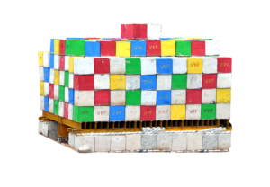
- The dead weight to be applied shall be 25% more than the maximum jacking force required.
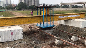
- Pile Loading Test shall be performed by applying compression load to the pile top by means of a hydraulic jack.
- The settlement shall be recorded by suitably positioned dial gauges.
- The Kent ledge consisting of frame capable of providing reaction shall be used.
- The C.G. of Kent ledge should be on the axis of the pile and the load applied by the jack should be co-axial with the pile

- The test can be initial or routine test.
- The load is applied in increments of 20% of the estimated safe load.
- Settlement is recorded for each 1hours and for each increment until the rate of settlement is less than 0.1 mm/hr.
- After reaching ultimate load, the load is released in decrements from the total load and recovery is measured until full rebound is established and next unload is done.
- After final unload the settlement is measured for 24 hrs to estimate full elastic recovery. Load settlement curve depends on the type of pile.

- Lateral load tests are desirable for horizontal displacement versus depth profiles.
- These profiles can be used in conjunction with lateral load versus displacement curves to calibrate lateral pile analysis programs.
- On deep foundations, it is desirable to obtain horizontal displacement versus depth profiles.
- These profiles can be used in conjunction with lateral load versus displacement curves to calibrate lateral pile analysis programs.
- In addition, the displacement versus depth curves can be used to determine bending moment versus depth profiles.
- This test method covers determination of the pullout strength of hardened concrete
- It’s done by measuring the force required to pull an embedded metal insert and the attached concrete fragment from a concrete test specimen or structure.
- The insert is either cast into fresh concrete or installed in hardened concrete.
- This test method does not provide statistical procedures to estimate other strength properties.

- The integrity test determines that a pile or shaft is free of major cracks and voids, prior to construction of the superstructure.
- The PIT may also be used to test pile integral, supporting existing bridges or towers.
- The PIT performs wave equation-based non-destructive foundation investigation.
- These tests may be performed by the pulse echo or transient response methods
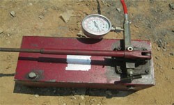
HYDRAULIC JACK
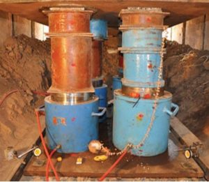
- Jack is used to lift heavy loads.
- They are mechanical and hydraulic in nature.
- Mechanical jacks are rated based on the lifting capacity.
- Hydraulic jacks are stronger.
- They lift higher and heavier loads include Bottle jacks and Floor jacks.
A jack is a device that uses force to lift heavy loads. The primary mechanism with which force is applied varies, depending on the specific type of jack, but is typically a screw thread or a hydraulic cylinder. Jacks can be categorized based on the type of force they employ: mechanical or hydraulic. Mechanical jacks, such as car jacks and house jacks, lift heavy equipment and are rated based on lifting capacity (for example, the number of tons they can lift). Hydraulic jacks tend to be stronger and can lift heavier loads higher, and include bottle jacks and floor jacks.
DIAL GUAGE
- Are precision primary measuring tools.
- They measure deck clearances, crankshaft thrust and straightness, lifter travel.
- The distance between two surfaces or small amounts of component travel.
- Dial indicators typically measure ranges from 0.25 mm to 50 mm.
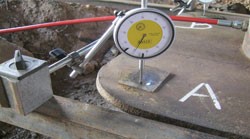 Dial indicators are one of the primary measuring tools used in precision engine building. They are typically used to measure deck clearances, crankshaft thrust and straightness, lifter travel and other measurements that involve the distance between two surfaces or small amounts of component travel. Dial indicators typically measure ranges from 0.25mm to 50mm (0.015in to 12.0in), with graduations of 0.001mm to 0.01mm (metric) or 0.00005in to 0.001in (imperial/customary).
PRESSURE GUAGE
- A pressure gauge measures pressure in a vacuum.
- It measures in both high and low vacuum, as well ultra-high vacuum.
- By employing several different types of gauges, one can measure continuous pressure between 10 mbar down to 10-11 mbar.
 Many techniques have been developed for the measurement of pressure and vacuum. Instruments used to measure pressure are called pressure gauges or vacuum gauges. A pressure gauge is used to measure the pressure in a vacuum—which is further divided into two subcategories: high and low vacuum (and sometimes ultra-high vacuum). The applicable pressure ranges of many of the techniques used to measure vacuums have an overlap. Hence, by combining several different types of gauge, it is possible to measure system pressure continuously from 10 mbar down to 10-11 mbar.